Power Seats Installation
 03-19-2010, 10:42 PM
#1
Power Seats Installation
As promised, I have finished my install of power seats in my 4runner.  This is another of my 'SR5 to LIMITED' threads. This will be a long thread with many pictures and will be over a couple of days as it takes time to write this up along with the pictures. Part of my goal is now to make my writes-ups along the line of "Mods for Dummies"
 This way if you have any mechnical abilities you should be able to do my mods with very little effort. So enjoy!
Power Seats
When I bought my 1998 4runner SR5 it was a very basic interior 4runner. I started what I referred to as my �SR5 to Limited� Mod. This is another installment on that journey. This write up is on installing powered seats. This write up is primarily for Gen 3 4runners. It should be applicable to 96-02 but just to be sure, I will address this install towards �96-�98.
I used the FSM Electrical Wiring Diagram applicable to 1998 model year. It should be pretty much the same for any of the 3rd Gens. So lets get started.
 Disclaimer: This write up is for educational purposes only. Any use or application of this procedure is done so at the risk of the installer/owner. The author and YotaTech are not responsible for any modifications done to any vehicle using these or any other related procedures contained in this or any other write up. Descriptions and photographs are the sole property and copyright of the author and may not be copied or distributed without written consent. Links to this article may be allowed but are protected by all US copyrights. Use of specific products along with any photographs of such items remains the copyrighted property of the copyright holder and is not an endorsement of any specific company or items.
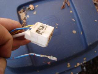
After locating your seats you will need to be sure to also get the pigtails for the seats out of the donor vehicle. The pigtail for the drivers seat is different from the pigtail that connects to the drivers manual seat. It is only a two wire pigtail/connector as it is only used for the seat belt warning light. The pigtail/connector for the powered seat is a 3 wire which in addition to the seat belt reminder, it also carries the 12vdc required to operate the seat.
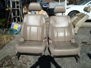
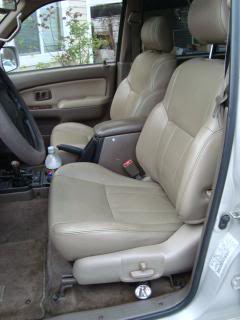
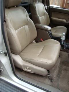
Here are the seats
While you are in the Yard I would recommend that you also find ascrapped 4runner to get the wire harness out of it. Try to get as much as you can including connectors, plugs wire runs etc. It will come in handy for many other projects. You will need at least three wires for this install so take your time in removal of the harness and connectors. You can tear it apart at home at your leasure.
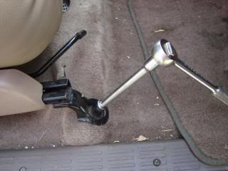
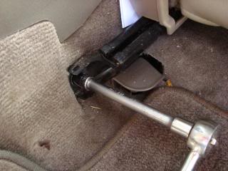
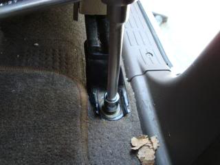
To begin, remove the 4 anchor bolts from the driver�s seat. You will need a 14mm socket and ratchet. A 6" extention is not necessary but desirable. I recommend that you manually slide the seat all the way back to access the front anchor bolts first.
Slide the seat fully forward to access the rear anchor bolts. Start with the inboard bolt then the outboard.
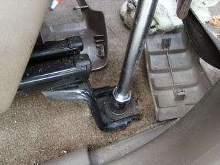
Tilt the seat slightly rearward to expose the seat belt connector.
Squeeze the connector at the end to release the connector from the seat.
Remove the seat.
Prepare the passenger seat by removing the anchor bolts in the same manner as the driver�s seat. Slide the seat fully back, remove the front anchor bolts.
Slide the seat fully forward and remove the rear anchor bolts.
This seat does NOT have a seat belt warning connector so you can just remove it from the truck.
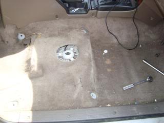
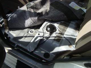
Remove the rear bench seat bottoms from both left and right sides. You will need a 12mm socket and ratchet.
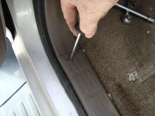
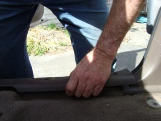
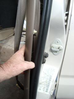
Remove the front door scuff plates. There are (4) Phillip�s head screws in each scuff plate.
Drivers side
Passenger side
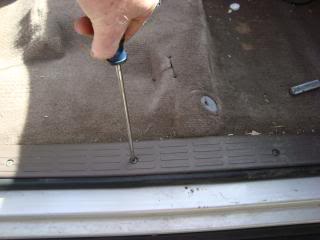
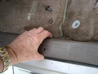
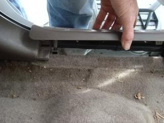
Each scuff plate has am indentation about the middle of the plate towards the inside. Slip your fingers under this cutout and move along the edge lifting as you go. The plate should �pop� loose. Grasp it firmly and pull upward clear of the door edge.
Remove the rear passenger door scuff plates. They are held in place with (2) Phillips head screws. Grasp the base of the plate and lift upward. Try to start near one end or the other. Be careful not to twist these too much as you can break the tabs at the base that hold the plate in position.
Remove the drivers side kick panel. This is accomplished by grasping the bottom rear edge and pulling toward yourself while also pulling slightly to the right.
Do the same with the passenger side kick panel. This is also the location of the ABS ECU.
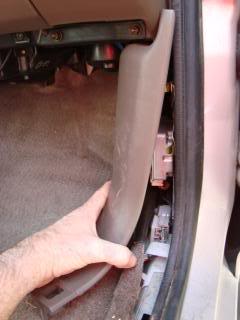
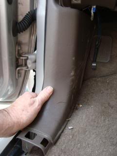
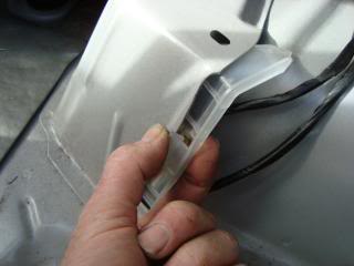
Remove the �B� pillar covers. Grasp the edge near the top of the cover and pull it away from the pillar. There are (3) white plastic pins that hold it in place.
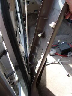
Remove the quarter panel cover on the driver�s side only. This makes it easier to pull the carpet out of the way to access connector J12. Lower the rear seat back by pulling the release knob on the top of the seat and lower it. Grasp the forward base of the cover and pull gently forward and up. It should pop off .
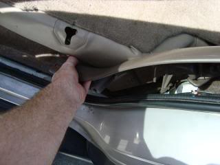
Pull the cover off the rear seat back anchor. Pull it straight out away from the side.
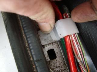
Begin to remove the carpet along the door edges by squeezing the white plastic clips then rotate them up and inward which will free them from the floor. Begin near the front edge of the driver�s door working your way to the rear driver�s side passenger door. Perform these same functions on the passenger side.
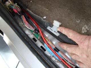
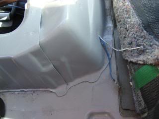
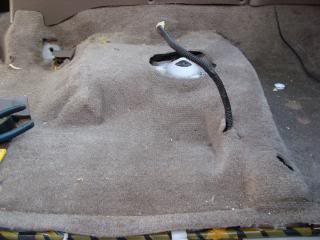
Pull the carpet in the rear driver�s side up and forward exposing the rear bench seat support.
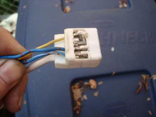
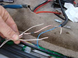
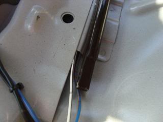
Pull the carpet clear of the driver�s side door area so as to expose the pigtail for the driver�s seat. This is a two wire connector. They are WHITE/RED (+) and WHITE/BLACK(-). Remove the electrical tape from the pigtail to expose these two wires. They will be the only two wires in the Driver�s seat pigtail/connector.
These two wires will be spliced into the new pigtail/connector for our powered seats. The only difference will be the new pigtail connector will have a third wire which will supply power to our driver�s seat.
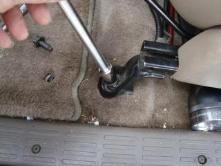
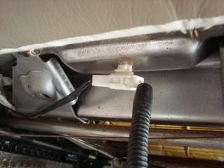
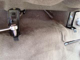
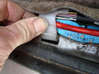
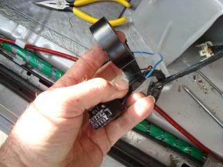
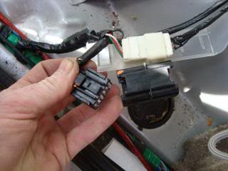
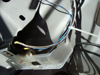
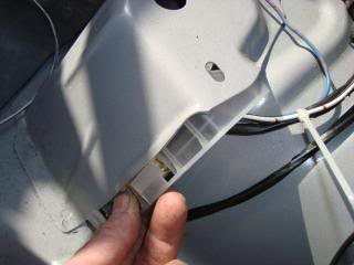
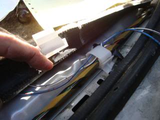
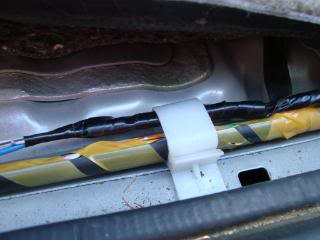
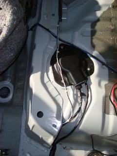
We will splice the new connector in using a stagger method so that the splice crimps will not be too large when we tape up our new pigtail. Next thing we need to do is provide a power source for the seat. In the powered seat 4runners from the factory they use what is called a �bridge connector�. What this is, is a special connector that has power/grounds at the connector but power is then �bridged� between several wires through this bridge connector. This connector is J12. J12 is located under the rear bench seat bottom on the driver�s side. There is a metal �box� area near the front corner of this bench seat bottom and you will find a translucent plastic hanger tucked inside this �box�
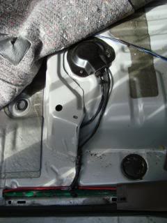
Using your fingers, lift one edge of the clip and begin to pull the hanger from its location. It is a bit long and runs along the entire length of this �box�.
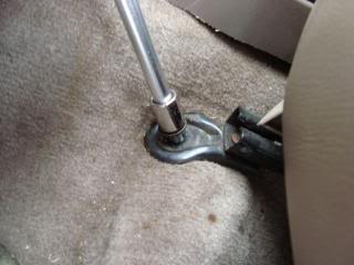
Pull J12 clear of the mounting location.
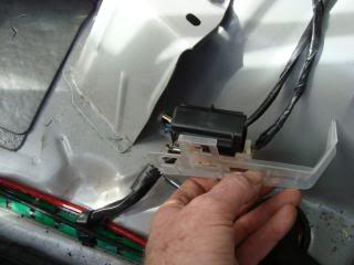
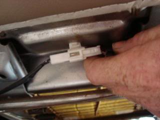
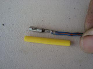
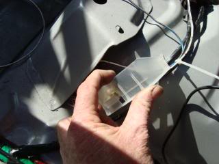
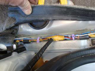
In the power seat versions there are three blue wires in J12 which would be the 3 wires on the right side, bottom row (+) and three white wires on the left side, bottom row (-). In the SR5 version without power seats the right most location is empty. What I did was using a scrap wire harness, I salvaged a blue wire with a box type connector.

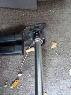
Insure the wire you salvage is long enough to reach the driver�s seat. If it isn�t, you'll have to splice in another piece of wire. Before you attempt to insert the new box connector and wire, you will need to "unlock" the connector. J12 is black and the connector lock is white. Using a small/jeweler's screw driver, gently lift the connector lock up slightly so that you can insert the new box/female connector. Now gently insert the box connector with wire into the empty third location in J12.
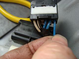
I should point out that there is dielectric grease in this connector. It�s pretty hard to screw this part up as the box connector will only go in one way. Do not force it. If it doesn�t want to just slide in then flip it over and try again. If the connector still doesn't want to slide in check the connector lock so make sure it is still up high enough to insert the new connector. Be sure to look at the other connectors. You should be able to see which way to orient the female box connector before pushing it into position. Once the connector is inserted press the connector lock down and ensure it is flush.
That's all for today, more to follow.
This is another of my 'SR5 to LIMITED' threads. This will be a long thread with many pictures and will be over a couple of days as it takes time to write this up along with the pictures. Part of my goal is now to make my writes-ups along the line of "Mods for Dummies" This way if you have any mechnical abilities you should be able to do my mods with very little effort. So enjoy!Power Seats
When I bought my 1998 4runner SR5 it was a very basic interior 4runner. I started what I referred to as my �SR5 to Limited� Mod. This is another installment on that journey. This write up is on installing powered seats. This write up is primarily for Gen 3 4runners. It should be applicable to 96-02 but just to be sure, I will address this install towards �96-�98.
I used the FSM Electrical Wiring Diagram applicable to 1998 model year. It should be pretty much the same for any of the 3rd Gens. So lets get started.
Disclaimer: This write up is for educational purposes only. Any use or application of this procedure is done so at the risk of the installer/owner. The author and YotaTech are not responsible for any modifications done to any vehicle using these or any other related procedures contained in this or any other write up. Descriptions and photographs are the sole property and copyright of the author and may not be copied or distributed without written consent. Links to this article may be allowed but are protected by all US copyrights. Use of specific products along with any photographs of such items remains the copyrighted property of the copyright holder and is not an endorsement of any specific company or items.After locating your seats you will need to be sure to also get the pigtails for the seats out of the donor vehicle. The pigtail for the drivers seat is different from the pigtail that connects to the drivers manual seat. It is only a two wire pigtail/connector as it is only used for the seat belt warning light. The pigtail/connector for the powered seat is a 3 wire which in addition to the seat belt reminder, it also carries the 12vdc required to operate the seat.
Here are the seats
While you are in the Yard I would recommend that you also find ascrapped 4runner to get the wire harness out of it. Try to get as much as you can including connectors, plugs wire runs etc. It will come in handy for many other projects. You will need at least three wires for this install so take your time in removal of the harness and connectors. You can tear it apart at home at your leasure.
To begin, remove the 4 anchor bolts from the driver�s seat. You will need a 14mm socket and ratchet. A 6" extention is not necessary but desirable. I recommend that you manually slide the seat all the way back to access the front anchor bolts first.
Slide the seat fully forward to access the rear anchor bolts. Start with the inboard bolt then the outboard.
Tilt the seat slightly rearward to expose the seat belt connector.
Squeeze the connector at the end to release the connector from the seat.
Remove the seat.
Prepare the passenger seat by removing the anchor bolts in the same manner as the driver�s seat. Slide the seat fully back, remove the front anchor bolts.
Slide the seat fully forward and remove the rear anchor bolts.
This seat does NOT have a seat belt warning connector so you can just remove it from the truck.
Remove the rear bench seat bottoms from both left and right sides. You will need a 12mm socket and ratchet.
Remove the front door scuff plates. There are (4) Phillip�s head screws in each scuff plate.
Drivers side
Passenger side
Each scuff plate has am indentation about the middle of the plate towards the inside. Slip your fingers under this cutout and move along the edge lifting as you go. The plate should �pop� loose. Grasp it firmly and pull upward clear of the door edge.
Remove the rear passenger door scuff plates. They are held in place with (2) Phillips head screws. Grasp the base of the plate and lift upward. Try to start near one end or the other. Be careful not to twist these too much as you can break the tabs at the base that hold the plate in position.
Remove the drivers side kick panel. This is accomplished by grasping the bottom rear edge and pulling toward yourself while also pulling slightly to the right.
Do the same with the passenger side kick panel. This is also the location of the ABS ECU.
Remove the �B� pillar covers. Grasp the edge near the top of the cover and pull it away from the pillar. There are (3) white plastic pins that hold it in place.
Remove the quarter panel cover on the driver�s side only. This makes it easier to pull the carpet out of the way to access connector J12. Lower the rear seat back by pulling the release knob on the top of the seat and lower it. Grasp the forward base of the cover and pull gently forward and up. It should pop off .
Pull the cover off the rear seat back anchor. Pull it straight out away from the side.
Begin to remove the carpet along the door edges by squeezing the white plastic clips then rotate them up and inward which will free them from the floor. Begin near the front edge of the driver�s door working your way to the rear driver�s side passenger door. Perform these same functions on the passenger side.
Pull the carpet in the rear driver�s side up and forward exposing the rear bench seat support.
Pull the carpet clear of the driver�s side door area so as to expose the pigtail for the driver�s seat. This is a two wire connector. They are WHITE/RED (+) and WHITE/BLACK(-). Remove the electrical tape from the pigtail to expose these two wires. They will be the only two wires in the Driver�s seat pigtail/connector.
These two wires will be spliced into the new pigtail/connector for our powered seats. The only difference will be the new pigtail connector will have a third wire which will supply power to our driver�s seat.
We will splice the new connector in using a stagger method so that the splice crimps will not be too large when we tape up our new pigtail. Next thing we need to do is provide a power source for the seat. In the powered seat 4runners from the factory they use what is called a �bridge connector�. What this is, is a special connector that has power/grounds at the connector but power is then �bridged� between several wires through this bridge connector. This connector is J12. J12 is located under the rear bench seat bottom on the driver�s side. There is a metal �box� area near the front corner of this bench seat bottom and you will find a translucent plastic hanger tucked inside this �box�
Using your fingers, lift one edge of the clip and begin to pull the hanger from its location. It is a bit long and runs along the entire length of this �box�.
Pull J12 clear of the mounting location.
In the power seat versions there are three blue wires in J12 which would be the 3 wires on the right side, bottom row (+) and three white wires on the left side, bottom row (-). In the SR5 version without power seats the right most location is empty. What I did was using a scrap wire harness, I salvaged a blue wire with a box type connector.
Insure the wire you salvage is long enough to reach the driver�s seat. If it isn�t, you'll have to splice in another piece of wire. Before you attempt to insert the new box connector and wire, you will need to "unlock" the connector. J12 is black and the connector lock is white. Using a small/jeweler's screw driver, gently lift the connector lock up slightly so that you can insert the new box/female connector. Now gently insert the box connector with wire into the empty third location in J12.
I should point out that there is dielectric grease in this connector. It�s pretty hard to screw this part up as the box connector will only go in one way. Do not force it. If it doesn�t want to just slide in then flip it over and try again. If the connector still doesn't want to slide in check the connector lock so make sure it is still up high enough to insert the new connector. Be sure to look at the other connectors. You should be able to see which way to orient the female box connector before pushing it into position. Once the connector is inserted press the connector lock down and ensure it is flush.
That's all for today, more to follow.
 03-20-2010, 02:09 AM
#2
Registered User
Join Date: May 2007
Location: Denver metro area-CO
Posts: 2,175
Likes: 0
Received 2 Likes
on
2 Posts
lurking along my friend....had no idea you were all set to get after this already. When the RitzyR gets his mind set he gets right after it. Me I talk about it for months and months....
safe to say these are not the heated and power leather seats from an 01-02 Limited?- I am thinking aloud ...
I can't say enough thanks about how much picture detail you provide on things like the clips and how they attach, those are the things I tend to break in my haste to get things done.
safe to say these are not the heated and power leather seats from an 01-02 Limited?- I am thinking aloud ...
I can't say enough thanks about how much picture detail you provide on things like the clips and how they attach, those are the things I tend to break in my haste to get things done.
03-20-2010, 08:07 AM
#3
You always make me chuckle Ron when I post one of my threads, you always have something positive to say and thats one of the reasons I post as I know it helps someone besides me! Definitely have to meet up some day ... As for the seats I wish they had come out of an 01-02 limited. They actually came out of a 97 limited that was REALLY trashed, I mean it took me well over two hours to get the passenger seat out. It had hit something at a rather high rate of speed right at the right front wheel as the right wheel well was pushed all the way up against the right front corner of the seat. I didn't think I was going to be able to get it out! Fortunately, after getting the anchor bolt under that corner out (and that was a contortionist nightmare
 ) I was able to finally get at the floor board to get the pigtail . Was a bit limited to how much I was going to get but it was enough. I'll try to finish up the write up later today. Stay tuned my friend!
 03-20-2010, 05:56 PM
#4
Part Two
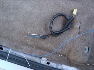
We left off installing the new power wire into J12

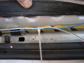
Now that is complete, you can check to see if you have 12vdc by measuring the end of the wire to ground using a multimeter. You should read somewhere around 12.4 or higher. Next using some electrical tape, wrap the group of wires that now include three blue wires (+) and the 2-3 white/black wires (-) so you have a clean bundle coming from the connector that plugs into J12.
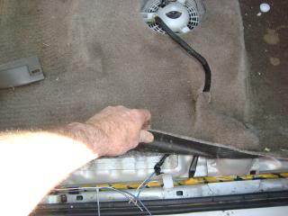
Begin routing the new seat power wire back along the wire path that runs along the edges of the doors.

If you have any problems getting the wire through one of the cable run grommets, if you squeeze it near the top then pull the lower edge away from the clip it should pop open, then just lay your new power wire in the cable run and then snap the clip back together.
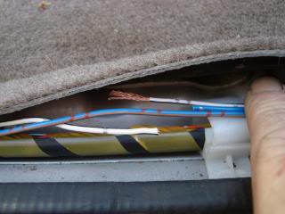
If you get them through all the clips and hold downs you should not have to wrap the new wires with electrical tape unless you would feel better about it. You can even use some small wire ties like this. I had to do this on the passenger side which is where this pic is from.
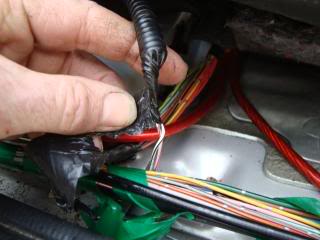
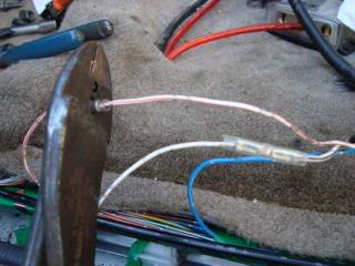
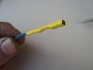
Route the new power wire until it is near the old seat belt warning wire. If you need to remove more of the tape to fully get at the old pigtail then do so now. Make the turn with the new power wire and give yourself about 4-6� of extra then cut the power wire. Remove the old pigtail by cutting the white/red and white/blue wires but be sure to leave a bit of extra so you have plenty to work with. On the new pigtail.
I staggered the blue wire about 4 inches from the two white wires for the seat belt warning. Over lay the new pigtail so you can see where you need to cut your wires so the splices will not be next to each other. Makes it easier to fit the splices inside the split loom of the new pigtail.
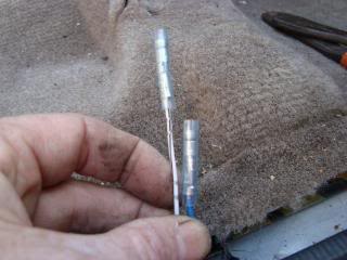
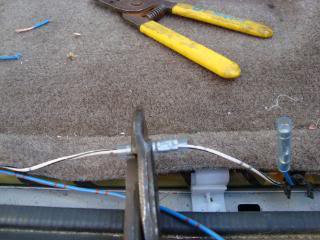
Strip the ends and prepare to attach the splices.
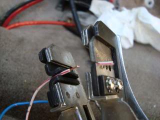
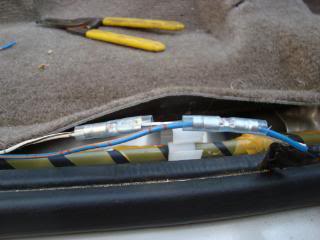
Crimp the spices and you are ready to tape up the new pigtail/connector
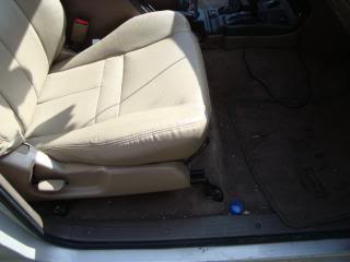
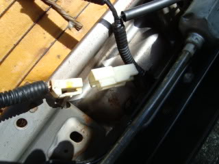
Tape up the new pigtail all the way to the floor cable run. As you are using the original seat belt warning wires from the harness you will need do nothing further to the drivers seat cabling. Install the new power driver�s seat and lift slightly to access the seat connector. Snap in the connector to our new power pigtail.
Install the seat anchors beginning with the rears. If the seat is not in the optimum position you should be able to operate the seat slide lever. Mine made some noise due to �junk yard debris� The grease on the rails and screw rods were cleaned but invariably you do some dirt or other small bits in there. Should not be a show stopper. If you have any concerns, clean the screws and rails before you install the seats.
Next we are going to tackle the passenger seat. In the OEM Limited where the wires are already installed the power for the passenger seat comes from a connector located just forward of the ABS ECU located behind the right passenger kick panel. Trying to route power and grounds through this connector is too difficult as this connector is not one of the special bridge connectors. If we were to use this connector we would also have to route another wire through the dash to unswiched power along with locating an adequate ground connection. Only J1-J16 are bridge connectors. Another bit to remember on the passenger seats is the fact there is not a passenger seat belt warning indicator at least on the �96-�98. As for the others you will need to check electrical FSM drawings.
In order to get unswitched power for our passenger seat we will once again access the J12 bridge connector. We used the empty location for our driver�s seat, but the pins go through the J12 connector and are in fact double pin. If you look into the opposite side of J12 where it has the other wires coming into it, there are pins coming out of the back side of the connector. If you remember when we installed the new power wire for our driver�s seat we removed the connector from J12 mounting connector by squeezing down the tab and pulling the connector out of the mounting connector.
The J12 mounting connector has double sided male pins inside of it. When you mate J12 connector with the mounting connector you now have all the pins available for installing another connector. As I did not have one, I decided to use the same box connectors and just attach them directly to the available pins.
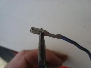
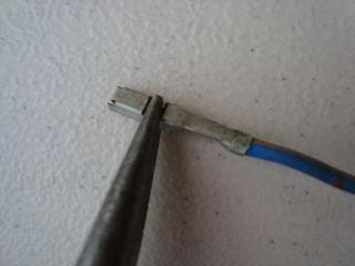
As I did with the driver�s side power wire, I scavenged two more wires with box type connectors.
Take each connector and using small needle nose pliers, bend down the two side flanges so they are flush with the box of the connector.
Cut two pieces of shrink tubing that will just fit over the connector approximately 1 & �� long.
Heat the shrink wrap so it forms a nice clean fitting insulation around the pin. Place the shrink tube so it is just flush with the end.
WARNING!
If you happen to touch one of the power pins to one of the ground pins you WILL blow the 30 amp fuse that supplies J12. That fuse is located under the dash on the driver�s side top of the fuse box and is pink in color.
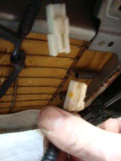
Look closely at the J12 connector and note the location of the blue power wires. You can verify power available with a multimeter and should read 12vdc+. Remember the warning above. You will want to install the wire onto one of these power pins. I chose the one at the far right bottom row. Slide the box connector over that pin. It should fit snuggly.
Using another box connector wire (I used a white one) perform the same to this connector as you did for the power wire. With the new GROUND wire locate the group of three (3) ground pins in the J12 connector. They will be the 3 left side pins. I selected the far left pin. Install the connector on this pin.
Carefully route the new wires out from the J12 mounting connector and use a small ty-wrap and secure them to the other wires that are coming from the adjacent connector located next to J12.
Carefully install the mounting connector back into its location inside of the floor box.
The upper most tip will give you a bit of a fit if you do not insert it first. The rest of the mount will then just slide right in place. Push it firmly into position ensuring that both the attaching clips mate correctly with the edge of the box.
You will note that just to the front of the tip of the jack handle stowage location there is an opening. Route the pair of new wires through here. There is a hole that goes down into the front panel of the rear seat bottoms.
Push the wires through until the reach the right side. You will be able to see them from the right side rear door where the jack is stowed. Reach inside the box area and route the wires through a round hole located near the far right side front edge of the seat bottom.
Pull the slack out of the wires and then continue over to the right side cable run. Begin to route the wires forward towards the location of the front passenger seat.
Route the wires along the cable run and secure it with small ty-wraps
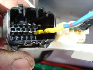
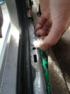
Once you reach the center area of the front passenger seat you can make your preparations to attach the passenger seat pigtail/connector.
Route the pigtail/connector through the cut slit in the carpet (already there) so you have the end of the pigtail near the wire ends.
Remember to stagger the wires so that the splices do not overlap each other.
Start with the shorter of the two wires and strip it. Install the splice. Measure up the second wire so that when you attach the splice it will be just forward of the first splice.
Strip and install the splice on the corresponding wire from our run. Repeat this a second time with the remaining wire.
Using electrical tape, begin on the pigtail/connector and wrap the wires until you pass over the splices. Route the new pigtail/connector through the near cable hold down ensuring the connector is back through the cut slit in the carpet.
Follow the wires back along the installation path and use small ty-wraps to secure the wires to the cable run.
Use a larger ty-wrap and affix the wires to the opening of the seat bottom so they are not loose in the void.
Ensure the wire pair is secure by using still more small ty-wraps along the path. If you do not have any more ty-wraps you could use duct tape to hold the wires firmly to the seat bottom if desired.
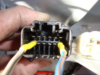
Install the seat. Tip it slightly backward exposing the connector and plug in our newly installed pigtail/connector.
 .
.
Install the anchor bolts and with power available you should be able to move the seat on its rails to secure it.
All that remains is to reinstall the carpet, securing the carpet hold downs to the locations along the door edges.
Install the �B� pillars into their respective locations.
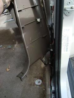
Install the removed quarter panel cover on the left side. Watch the attaching nylon pins. Usually the one located near the scuff plate location stays in place. That should not pose a problem if when you install the panel you place it low in position and then slip it backward. This will also cause you to pull the back edge out so the slot for the seat anchor will fit though the slot hole. This will aid in lining up the other nylon pin. Once in position, give it firm wrap with your fist or a rubber mallet. Do not hit it too hard as if its not properly lined up you will mash it over and then it gets really fun trying to get it in place.
Install the removed kick panels to both sides if you removed them.
Install the door scuff plates. A word of warning on installing the scuff plates; the base of each of these plates has a double tabbed end that the securing screws go into. They spread out holding the scuff plate in the door frame base. Make sure that the tabs are not bent over which will make it impossible to correctly install the scuff plates and can break one of the tabs off. Screw then into place.
Install the rear bench seats using the 12 mm bolts you removed earlier.
Installation is complete!
We left off installing the new power wire into J12
Now that is complete, you can check to see if you have 12vdc by measuring the end of the wire to ground using a multimeter. You should read somewhere around 12.4 or higher. Next using some electrical tape, wrap the group of wires that now include three blue wires (+) and the 2-3 white/black wires (-) so you have a clean bundle coming from the connector that plugs into J12.
Begin routing the new seat power wire back along the wire path that runs along the edges of the doors.
If you have any problems getting the wire through one of the cable run grommets, if you squeeze it near the top then pull the lower edge away from the clip it should pop open, then just lay your new power wire in the cable run and then snap the clip back together.
If you get them through all the clips and hold downs you should not have to wrap the new wires with electrical tape unless you would feel better about it. You can even use some small wire ties like this. I had to do this on the passenger side which is where this pic is from.
Route the new power wire until it is near the old seat belt warning wire. If you need to remove more of the tape to fully get at the old pigtail then do so now. Make the turn with the new power wire and give yourself about 4-6� of extra then cut the power wire. Remove the old pigtail by cutting the white/red and white/blue wires but be sure to leave a bit of extra so you have plenty to work with. On the new pigtail.
I staggered the blue wire about 4 inches from the two white wires for the seat belt warning. Over lay the new pigtail so you can see where you need to cut your wires so the splices will not be next to each other. Makes it easier to fit the splices inside the split loom of the new pigtail.
Strip the ends and prepare to attach the splices.
Crimp the spices and you are ready to tape up the new pigtail/connector
Tape up the new pigtail all the way to the floor cable run. As you are using the original seat belt warning wires from the harness you will need do nothing further to the drivers seat cabling. Install the new power driver�s seat and lift slightly to access the seat connector. Snap in the connector to our new power pigtail.
Install the seat anchors beginning with the rears. If the seat is not in the optimum position you should be able to operate the seat slide lever. Mine made some noise due to �junk yard debris� The grease on the rails and screw rods were cleaned but invariably you do some dirt or other small bits in there. Should not be a show stopper. If you have any concerns, clean the screws and rails before you install the seats.
Next we are going to tackle the passenger seat. In the OEM Limited where the wires are already installed the power for the passenger seat comes from a connector located just forward of the ABS ECU located behind the right passenger kick panel. Trying to route power and grounds through this connector is too difficult as this connector is not one of the special bridge connectors. If we were to use this connector we would also have to route another wire through the dash to unswiched power along with locating an adequate ground connection. Only J1-J16 are bridge connectors. Another bit to remember on the passenger seats is the fact there is not a passenger seat belt warning indicator at least on the �96-�98. As for the others you will need to check electrical FSM drawings.
In order to get unswitched power for our passenger seat we will once again access the J12 bridge connector. We used the empty location for our driver�s seat, but the pins go through the J12 connector and are in fact double pin. If you look into the opposite side of J12 where it has the other wires coming into it, there are pins coming out of the back side of the connector. If you remember when we installed the new power wire for our driver�s seat we removed the connector from J12 mounting connector by squeezing down the tab and pulling the connector out of the mounting connector.
The J12 mounting connector has double sided male pins inside of it. When you mate J12 connector with the mounting connector you now have all the pins available for installing another connector. As I did not have one, I decided to use the same box connectors and just attach them directly to the available pins.
As I did with the driver�s side power wire, I scavenged two more wires with box type connectors.
Take each connector and using small needle nose pliers, bend down the two side flanges so they are flush with the box of the connector.
Cut two pieces of shrink tubing that will just fit over the connector approximately 1 & �� long.
Heat the shrink wrap so it forms a nice clean fitting insulation around the pin. Place the shrink tube so it is just flush with the end.
WARNING!If you happen to touch one of the power pins to one of the ground pins you WILL blow the 30 amp fuse that supplies J12. That fuse is located under the dash on the driver�s side top of the fuse box and is pink in color.
Look closely at the J12 connector and note the location of the blue power wires. You can verify power available with a multimeter and should read 12vdc+. Remember the warning above. You will want to install the wire onto one of these power pins. I chose the one at the far right bottom row. Slide the box connector over that pin. It should fit snuggly.
Using another box connector wire (I used a white one) perform the same to this connector as you did for the power wire. With the new GROUND wire locate the group of three (3) ground pins in the J12 connector. They will be the 3 left side pins. I selected the far left pin. Install the connector on this pin.
Carefully route the new wires out from the J12 mounting connector and use a small ty-wrap and secure them to the other wires that are coming from the adjacent connector located next to J12.
Carefully install the mounting connector back into its location inside of the floor box.
The upper most tip will give you a bit of a fit if you do not insert it first. The rest of the mount will then just slide right in place. Push it firmly into position ensuring that both the attaching clips mate correctly with the edge of the box.
You will note that just to the front of the tip of the jack handle stowage location there is an opening. Route the pair of new wires through here. There is a hole that goes down into the front panel of the rear seat bottoms.
Push the wires through until the reach the right side. You will be able to see them from the right side rear door where the jack is stowed. Reach inside the box area and route the wires through a round hole located near the far right side front edge of the seat bottom.
Pull the slack out of the wires and then continue over to the right side cable run. Begin to route the wires forward towards the location of the front passenger seat.
Route the wires along the cable run and secure it with small ty-wraps
Once you reach the center area of the front passenger seat you can make your preparations to attach the passenger seat pigtail/connector.
Route the pigtail/connector through the cut slit in the carpet (already there) so you have the end of the pigtail near the wire ends.
Remember to stagger the wires so that the splices do not overlap each other.
Start with the shorter of the two wires and strip it. Install the splice. Measure up the second wire so that when you attach the splice it will be just forward of the first splice.
Strip and install the splice on the corresponding wire from our run. Repeat this a second time with the remaining wire.
Using electrical tape, begin on the pigtail/connector and wrap the wires until you pass over the splices. Route the new pigtail/connector through the near cable hold down ensuring the connector is back through the cut slit in the carpet.
Follow the wires back along the installation path and use small ty-wraps to secure the wires to the cable run.
Use a larger ty-wrap and affix the wires to the opening of the seat bottom so they are not loose in the void.
Ensure the wire pair is secure by using still more small ty-wraps along the path. If you do not have any more ty-wraps you could use duct tape to hold the wires firmly to the seat bottom if desired.
Install the seat. Tip it slightly backward exposing the connector and plug in our newly installed pigtail/connector.
.Install the anchor bolts and with power available you should be able to move the seat on its rails to secure it.
All that remains is to reinstall the carpet, securing the carpet hold downs to the locations along the door edges.
Install the �B� pillars into their respective locations.
Install the removed quarter panel cover on the left side. Watch the attaching nylon pins. Usually the one located near the scuff plate location stays in place. That should not pose a problem if when you install the panel you place it low in position and then slip it backward. This will also cause you to pull the back edge out so the slot for the seat anchor will fit though the slot hole. This will aid in lining up the other nylon pin. Once in position, give it firm wrap with your fist or a rubber mallet. Do not hit it too hard as if its not properly lined up you will mash it over and then it gets really fun trying to get it in place.
Install the removed kick panels to both sides if you removed them.
Install the door scuff plates. A word of warning on installing the scuff plates; the base of each of these plates has a double tabbed end that the securing screws go into. They spread out holding the scuff plate in the door frame base. Make sure that the tabs are not bent over which will make it impossible to correctly install the scuff plates and can break one of the tabs off. Screw then into place.
Install the rear bench seats using the 12 mm bolts you removed earlier.
Installation is complete!
 02-18-2015, 06:42 PM
#7
Registered User
Join Date: May 2007
Location: Denver metro area-CO
Posts: 2,175
Likes: 0
Received 2 Likes
on
2 Posts
Still lurking and this is going to exceed my abilities. Reaj there are some decent 98 Limited seats on Denver craigslist now. Please buy them so I won't keep tempting myself....
Trending Topics
01-08-2017, 08:01 PM
#8
Registered User

Join Date: Oct 2007
Posts: 5
Likes: 0
Received 0 Likes
on
0 Posts
Thank you so much for this detailed guide. For my 1996 SR5 build, I found a salvaged 2001 Limited that hadn't been processed yet. I went to town on it. Took all of the harness, seats, door panels, heated seat switches, center console etc.
Question: any guidance for the heated seat connections? How many amp fuse should I plan for? Is there a spare place in the OEM fuse block or should I get creative? Thanks. I do have the FSM and electrical manual as well.
Here's my build:
https://www.facebook.com/media/set/?...1&l=d86dfc2766
Question: any guidance for the heated seat connections? How many amp fuse should I plan for? Is there a spare place in the OEM fuse block or should I get creative? Thanks. I do have the FSM and electrical manual as well.
Here's my build:
https://www.facebook.com/media/set/?...1&l=d86dfc2766
01-08-2017, 08:31 PM
#9
Good to see this is still usable . Its getting harder and harder to find leather seats (manual or electric, AND with heated seats that are not totally trashed. I need to replace the seat bottom on my driver side, it has split so I need to look at that. Wish I had found a set from the 01/02 limited, heated seats would be a BIG bonus right now!. Only recommendation is to get a copy of the pages concerning the wiring for the heated version of the seats and see where the heat wires are routed, connector ground etc. Very well could go to J12. The normal SR5 has a few openings in it for power, such is the case for the normal power for the seats. I would like to see what you found out so feel free to update the thread with what you found. Best of luck. Glad the thread helped you out
The following users liked this post:
SergioV22 (04-11-2024)
04-11-2024, 11:16 PM
#10

Looking for some help
Good to see this is still usable . Its getting harder and harder to find leather seats (manual or electric, AND with heated seats that are not totally trashed. I need to replace the seat bottom on my driver side, it has split so I need to look at that. Wish I had found a set from the 01/02 limited, heated seats would be a BIG bonus right now!. Only recommendation is to get a copy of the pages concerning the wiring for the heated version of the seats and see where the heat wires are routed, connector ground etc. Very well could go to J12. The normal SR5 has a few openings in it for power, such is the case for the normal power for the seats. I would like to see what you found out so feel free to update the thread with what you found. Best of luck. Glad the thread helped you out

Thread
Thread Starter
Forum
Replies
Last Post
Johntom240
General Electrical & Lighting Related Topics
7
07-13-2015 12:18 AM
icentropy
86-95 Trucks & 4Runners
4
07-09-2015 02:12 PM


