
been thinkin of a better cold air intake setup...
 08-26-2013, 08:58 AM
#81
Registered User
Gamefreak - did you see the Cressida lid? I'm debating whether it would make the most sense just to swap it whole and lose the connections or cut and then glue/plastic weld the two pieces back together... (But I really like the S&B box -- it looks good and would probably be a cleaner install of a larger AFM regardless).
The bigdrawback of the supra filter housing is that if any of it gets submerged, it's sucking water and destroying your engine. And you lose the ability to use the stock deflector...
The bigdrawback of the supra filter housing is that if any of it gets submerged, it's sucking water and destroying your engine. And you lose the ability to use the stock deflector...
The supra AFM draws from the center of the back wall, so some water in it wouldn't damage it. The top draw of the stock box is ideal, but we're talking a difference of about 2-3 inches. It doesn't flood here and I don't do any crazy off-roading so I'm not too worried.
 08-26-2013, 03:08 PM
#82
Registered User
Project links:
https://www.yotatech.com/forums/f116...l#post52109103
https://www.yotatech.com/forums/f116...l#post52109836
https://www.yotatech.com/forums/f116...l#post52110346
Alright,
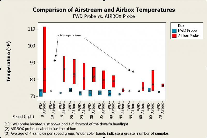
After getting the temp. probes setup and my "data recorders" briefed we set out on our information collection adventure. We drove around for about an hour collecting data points both in-town and on the highway. There was roughly a 60/40 mix of hills to flat lands on our route. One recorder monitored pressure-drop readings, the other monitored temperature readings. Sample sets of data were desired for every five mph increments from 0 to 70 mph.
Lessons learned:
Real-world conclusions:
Now we know that a properly designed cold-air intake will make a difference to benefit beyond the OEM intake system (K&N drop-in filter included). Next, we should investigate the cost-benefit relationship for the many cool ideas presented in this thread.

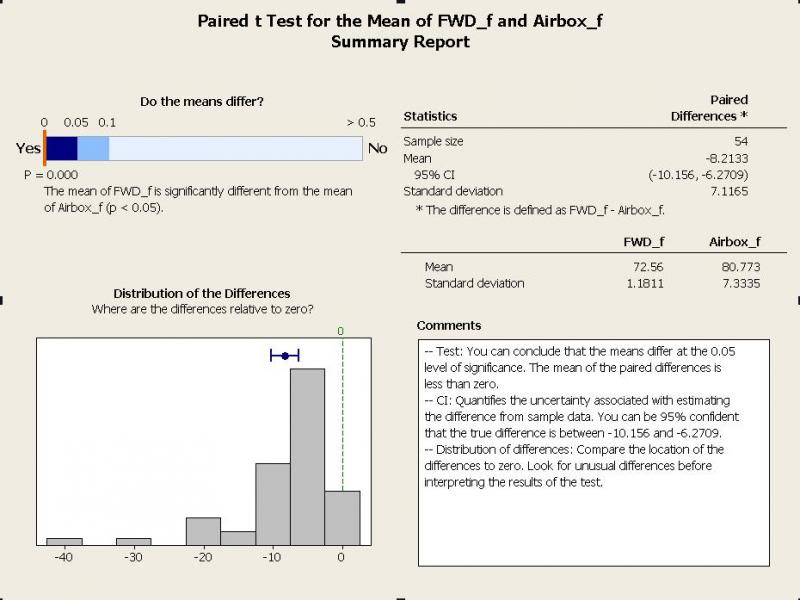
A paired-t test was calculated for the means of the FWD probe and the AIRBOX probe.
Statistical conclusions:

https://www.yotatech.com/forums/f116...l#post52109103
https://www.yotatech.com/forums/f116...l#post52109836
https://www.yotatech.com/forums/f116...l#post52110346
Alright,
After getting the temp. probes setup and my "data recorders" briefed we set out on our information collection adventure. We drove around for about an hour collecting data points both in-town and on the highway. There was roughly a 60/40 mix of hills to flat lands on our route. One recorder monitored pressure-drop readings, the other monitored temperature readings. Sample sets of data were desired for every five mph increments from 0 to 70 mph.
Lessons learned:
- The number of sample sets depended on available terrain and traffic congestion.
- A sufficient number of samples were not obtained for certain speeds based on the flow of traffic. Additional sorties would be needed to round-out the missing data sets.
- A data recorder such as this system, would be much less demanding with a trade-off in cost. This system would also reduce possible transcription error.
- The inherent variability between the two temperature instruments was present but would not alter the conclusions of this study.
- The next study should include engine rpm also collected in real-time.
- The next study should consider the boundary airflow pattern for this vehicle when locating the external (FWD) temperature probe. An assumption is that turbulent air will adversely affect true air stream temperature.
Real-world conclusions:
- That having an intake fully sealed from the engine bay with an external pickup point will make a substantial difference in intake temperature.
- That ambient (external airstream) temperature generally remains constant or slowly changes throughout the day.
- That time spent at a slower speed, i.e. zero mph, will also see an increase in airbox air temperature. For example, sitting at a traffic light.
- That increasing speed will also decrease airbox temperature to a certain extent. This is most evident between 0 and 45 mph.
- That a higher speed, that is to say airflow, does not automatically mean lower airbox temperature, e.g. at highway speeds going up hills or inclines meant a greater load on the engine with a subsequent higher range of temperature in the airbox.
- That the average air stream temperature for the test was 73�F, and the average airbox temperature for the test was 81�F.
Now we know that a properly designed cold-air intake will make a difference to benefit beyond the OEM intake system (K&N drop-in filter included).
Next, we should investigate the cost-benefit relationship for the many cool ideas presented in this thread. A paired-t test was calculated for the means of the FWD probe and the AIRBOX probe.
Statistical conclusions:
- That some data pairs are unusual compared to others, could represent special cause variation. Upon inspection, these pairs occurred while waiting at traffic signals; airbox temperatures increased dramatically
- That since sample sizes (sets) were greater than 20, normality is not an issue
- That the sample is sufficient to detect a difference between the means
Last edited by skipper0802; 08-26-2013 at 03:17 PM. Reason: Added prior links to project setup
08-26-2013, 04:14 PM
#83
Registered User
Someone was paying attention in stats class!
That seals the deal for me. I'm loading up on supplies and going to find a way to open up the air passageways and get COLD air in my supra air box. I looked over it again and it shouldn't be too hard, just cut out some foam, seal it and drill some holes like RSR did.
That seals the deal for me. I'm loading up on supplies and going to find a way to open up the air passageways and get COLD air in my supra air box. I looked over it again and it shouldn't be too hard, just cut out some foam, seal it and drill some holes like RSR did.
08-26-2013, 04:42 PM
#84
Registered User
Improve improve improve
Someone was paying attention in stats class!
That seals the deal for me. I'm loading up on supplies and going to find a way to open up the air passageways and get COLD air in my supra air box. I looked over it again and it shouldn't be too hard, just cut out some foam, seal it and drill some holes like RSR did.
That seals the deal for me. I'm loading up on supplies and going to find a way to open up the air passageways and get COLD air in my supra air box. I looked over it again and it shouldn't be too hard, just cut out some foam, seal it and drill some holes like RSR did.
In the meanwhile, I'll continue to finish the manometer/pressure drop documentation and measurements portion of the project.
Last edited by skipper0802; 08-26-2013 at 10:46 PM. Reason: spell check
08-26-2013, 09:59 PM
#85
Registered User

Skipper -- Really appreciate the scientific approach and your time and gas!
Looking forward to the pressure tests. That should be really enlightening.
I found the engine bay temp at air intake at idle was 50* above ambient when parked at idle and 30* above ambient at parked, but didn't have a good way to quantify speeds. Really interesting to see temps climb measurably at high speeds under load -- when you need that additional oomph the most...
If you're looking for outside air only and avoid water, a snorkel setup is your best bet.
I suppose some sort of ram air hood scoop would work, but our engine is pretty tight to the hood over the intake plenum so might be tough to execute.
You could go like the next generation and route the air intake into the fender -- but note you'll lose any rammed air function/benefits of the factory setup at high speeds.
The stock factor setup actually has 3 to 4 or 4 1/2 or so primary points of water deflection prior to intake, and you should be able to submerge up to 1/3rd or so of you headlight without serious water suck damage...
Points of deflection/drainage:
1. Headlight and front grille (exterior drainage down)
2. Front frame (exterior drainage down)
3. Air deflector
4. Air box filter being raised above air intake.
4 1/2. The air box low ridges look to be specifically designed to catch and hold temporary water until it evaporates/drains (drainage hole in the box). Not a perfect solution but more than just a box.
And the factory setup has 1 to 1.5 add'l protections than the S&B for instance, which has even more protections for than K&N or other cone slapons...
Last edited by RSR; 08-26-2013 at 10:09 PM.
08-26-2013, 10:02 PM
#86
Registered User
Someone was paying attention in stats class!
That seals the deal for me. I'm loading up on supplies and going to find a way to open up the air passageways and get COLD air in my supra air box. I looked over it again and it shouldn't be too hard, just cut out some foam, seal it and drill some holes like RSR did.
That seals the deal for me. I'm loading up on supplies and going to find a way to open up the air passageways and get COLD air in my supra air box. I looked over it again and it shouldn't be too hard, just cut out some foam, seal it and drill some holes like RSR did.
08-26-2013, 10:07 PM
#87
Registered User
Just saw it now. That could work, assuming that's the lid from the V6 engine and not the 4 cylinder. The 4 cylinder VAFM is the same size as our stock ones. It would take a good bit of modding to make it work, and you'd also need to enlarge the size of the air box opening, making the spoiler obsolete.
The supra AFM draws from the center of the back wall, so some water in it wouldn't damage it. The top draw of the stock box is ideal, but we're talking a difference of about 2-3 inches. It doesn't flood here and I don't do any crazy off-roading so I'm not too worried.
The supra AFM draws from the center of the back wall, so some water in it wouldn't damage it. The top draw of the stock box is ideal, but we're talking a difference of about 2-3 inches. It doesn't flood here and I don't do any crazy off-roading so I'm not too worried.
08-26-2013, 10:17 PM
#88
Registered User
Thread Starter
Join Date: Jun 2013
Location: Texas
Posts: 232
Likes: 0
Received 0 Likes
on
0 Posts
I must say I've been happy so far. More power then I had before default. Maybe someone can help figure this out for the he'll if it..before I had 35" tires and I was getting roughly 250- 300 miles it off full tank. After upgrading tires to 37" and doing the s&b swap ive learned my mileage has remained unchanged. Any thoughts on this?? Also I plan on fabricating a ram air thru grill that helps with submersion as well as strictly getting outside untouched cooler air. It will happen if I have anything to say about it!
08-29-2013, 10:26 PM
#89
Registered User
vital22re posted this video over here: https://www.yotatech.com/forums/f116...l#post52113263
Found it relevant:
Found it relevant:
08-30-2013, 07:12 AM
#90
Registered User
It's only after I did the supra swap that I'm noticing the heat issues. Maybe my IAT sensor on my old VAFM was on its way out!
RSR, in regards to that video, that's spot on to what I've noticed with newer vehicles. We have a 2011 Nissan Altima Hybrid that puts out 200 HP (not much of a hybrid
 ) and all I've read and seen other proof that "Cold Air Intakes" aren't that, they pull air from the engine bay. The stock setup on our Altima draws in cold air from behind the grill on top of the radiator, so anything else would lose power, like what they demonstrate. There's no restriction at WOT (well, sorta WOT since the electric engine requires no air...).
But that's 2011. Back in 1991 when my truck was made, was this known well enough by manufacturers? The cold air with the spoiler on the stock setup is restrictive at WOT (confirmed by the first part of this thread) but the "CAI" route has flaws if it gets hot. I supposed if you live in Alaska a CAI would work ok. In my case with the Supra setup, I've already had some noticeable gains. Those could be further increased if I can change my setup since it for all intensive purposes, acting like a CAI at the moment.
08-30-2013, 07:56 AM
#91
Registered User
08-30-2013, 08:32 AM
#92
Registered User
Interesting correlation between their temp. data and mine concerning factory air setup vs. an external CAI pod filter. About a 14 kw (~18.8 HP) difference.
Concerns:
I like the factory intake system because it's a good design considering ALL environmental factors and intended usage. I don't classify it as a CAI because it still draws engine bay air. Still, I still like to see an integration of a dedicated external air pick-up point, and a reduction in pressure restriction.
What's the bottom line? Can you really make a change to your system and claim a particular effect? Not without backing it up with proper information IMO. Let's continue with due diligence and make some good decisions, and of course, continue to have fun.
Concerns:
- Is the car driveable with the external pod? Not really. You could mount the pod on a boom, but you might get some strange looks

- What about driving in inclement weather? Better consult with the Navy about IC engines and weather--your car's about to become a submarine

- Is a 8.3% improvement noticeable on the road? That would depend on the driver's perception. Still 8.3% though.

- How would this improvement affect mpg? Unknown. We'd need a longitudinal study for that answer.

I like the factory intake system because it's a good design considering ALL environmental factors and intended usage. I don't classify it as a CAI because it still draws engine bay air. Still, I still like to see an integration of a dedicated external air pick-up point, and a reduction in pressure restriction.
What's the bottom line? Can you really make a change to your system and claim a particular effect? Not without backing it up with proper information IMO. Let's continue with due diligence and make some good decisions, and of course, continue to have fun.
Last edited by skipper0802; 08-30-2013 at 08:45 AM. Reason: added comment
08-30-2013, 11:50 AM
#94
Registered User

 08-30-2013, 12:12 PM
#95
Registered User
I doubt anyone has those restriction #s. W/ the snorkel, you eliminate most H20 issues and draw cold air, but with the add'l restriction of the snorkel setup. The plastic snorkel isn't equivalent flow to mandrel bent exhaust tubing, which really is the best bends setup for optimized flow... On the next gen trucks, they have an equivalent elbow to snorkel into the fender and that is a very real and noticeable point of restriction according to folks reports.
08-30-2013, 12:16 PM
#96
Registered User
How do you figure the factory system draws engine bay air w/ all components installed? It's specifically designed not to. Yes, there's a small gap at the top of the deflector (which I sealed in my project), the bottom fits tight to the body, and the sides have foam to seal the gap as well... Point being, it's designed to draw outside, not inside, air and is accordingly a true cold air intake as I describe it.
08-30-2013, 01:31 PM
#97
Registered User
How do you figure the factory system draws engine bay air w/ all components installed? It's specifically designed not to. Yes, there's a small gap at the top of the deflector (which I sealed in my project), the bottom fits tight to the body, and the sides have foam to seal the gap as well... Point being, it's designed to draw outside, not inside, air and is accordingly a true cold air intake as I describe it.
- That the OEM box is drawing warmer air from the engine bay in addition to the grill pick-up point.
- That external air is drawn into and radiantly warmed by the intake components themselves.
Since I didn't have enough temp. sensors to measure the second case, I cannot draw conclusions for this situation. However, considering the velocity of the air flow and the distance traveled (~11" from pick-up point to center air box) I'm very skeptical that an ambient, external flow can be warmed in this manner to fully account for the temperature differences observed.
On the other hand, the data clearly shows a reduction of average temperature and range of temperature inside the air box as vehicle speed increases. I see two possible causes for this:
- That a larger percentage of cooler, external air is being drawn
- That engine bay air temperature is reduced by the increased air flow through the grill, reducing the temperature of the intake components thereby reducing the temperature in the air box by conduction
- Or, that the increased air flow through the grill reduces the engine bay air temperature, which we see as reduced air temperature in the air box.
That's why I don't consider the OEM intake system a bonafide "cold air intake" when the air that it inducts is warmer than the ambient air stream.
08-30-2013, 01:55 PM
#98
Registered User
I see all this attention being put towards bringing in cold air. But, nobody has seemed to realize the fact that the air travels down the system and is warmed by the intake anyways. Go put your hand on top of the intake manifold of a 22RE. It is hot, due to the heat sink created by the engine. What's the point of bringing in cold air if is just gets heated later on in the system?
To make this a viable option, the air needs to be the same temperature at the point of combustion as it was when it first entered the system.
All these graphs and theories are pointless if the entire system is not looked at.
To make this a viable option, the air needs to be the same temperature at the point of combustion as it was when it first entered the system.
All these graphs and theories are pointless if the entire system is not looked at.
08-30-2013, 01:57 PM
#99
Registered User
Oh, okay, gotcha.
I think when you look at the intake like that, any air intake will not be a true cold air intake as the components themselves will always be warmed by the ambient air in the engine bay. As speed increases, you have to be going at a decent rate to move all the heat the stock crossover allows to radiate into the engine bay... The 3vze is definitely one of the hotter engine bays I've worked on -- and that's including some cars with turbos too...
And also why I think that the biggest gain from the headers/crossover delete is actually b/c of heat removal, not improved air/exhaust flow.
I think I found that in my quick and dirty temp test, the ambient temp in the engine bay after running at highway speeds and turning engine off was 130* (or 40* higher than 90*F outside air). So to drop the heat/remove the heat from the airbox itself, talking about it's physical plastic (remember that your thermometer probe was laying on top of the plastic and there's a good 1/2" air space between box and engine bay frame/body that's constantly going to be reheating the box's plastic which will be heating air and seen on your temp probe), I imagine you have to be getting a pretty decent flow of air to drop. So it's an ambient heat transfer to intake components, not a problem with drawing hot from engine bay. Or at least that's my opinion.
I think that makes sense. You're saying the temp shows that air in airbox is above outside ambient/airbox doesn't fully isolate intake air from engine bay heat. I'm agreeing to the point that there's ambient heat transfer, but saying factory is overwhelming drawing in cold air and that in and of itself matters... Essentially, by drawing outside air, you're still starting whatever the difference is in degrees from engine bay and outside ahead of drawing from engine bay alone... And with engine running and at idle, I found engine bay to be 50* above outside air. Outside air will heat up, but it also helps the intake to cool down (doubtful it ever reaches the same temp as engine bay air). Drawing just engine bay air keeps everything hot/at same temp as engine bay all the time...
The plenum on mine gets near burn temps -- and that's actually what majorly helped it to be cleaned w/ the Amsoil Intake Cleaner spray. The ISR arm drops down to w/in an inch or two of drivers side header and gets crazy hot -- tried to grab that plastic elbow box once to move it out of the way -- and hot dang! And the rest of the air mechanism is in the engine bay and also getting heated by ambient air. I think the ISR delete w/ some sort of heat insulation on the new intake arm is pretty critical for minimizing the heating of intake air. You could probably insulate your airbox and whatnot if you really want to, but I'm not sure how much gain that would give you, but I guess you could test!
Last edited by RSR; 08-30-2013 at 02:03 PM.
08-30-2013, 02:09 PM
#100
Registered User
Here's some dynos on the elbow:
http://www.gadgetonline.com/AirInduc...ove the Elbow:
And note that this whole elbow removal ends up killing the "cold air intake" instead drawing engine air, but due to extent of the restriction, HP gains are seen. I think the same is probably the case w/ a snorkel...
The popular next gen deckplate mod is a different route to accomplish the same:
http://home.ezonline.net/~jnburtman/deckplate.html
http://www.gadgetonline.com/AirInduc...ove the Elbow:
Configuration 1st 2nd 3rd
Run 9 Stock Box No Front 173.3 HP 205.5 HP 210.8 HP
Run 8 Stock Box No Elbow 170.7 HP 205.1 HP 210.8 HP
Run 7 Stock Box 168.8 HP 199.5 HP 201.8 HP
Run 9 Stock Box No Front 173.3 HP 205.5 HP 210.8 HP
Run 8 Stock Box No Elbow 170.7 HP 205.1 HP 210.8 HP
Run 7 Stock Box 168.8 HP 199.5 HP 201.8 HP
The popular next gen deckplate mod is a different route to accomplish the same:
The cap also makes an easy way to dyno test this mod. Cap on, cap off, which take about 5 seconds. From what I hear, this mod adds about 7 HP on the dyno powered from a naturally aspirated Tacoma. The Tacoma uses the same 3.4 liter engine as the 4Runner. Remember, when the dyno is done the truck is at a standstill. When moving, the warm engine bay will be flushed with cooler air. The cool air from under the headlights and front grille should give even better results.
Last edited by RSR; 08-30-2013 at 02:15 PM.


