
90 yota 4 runner , bogs bad on acceleration
 02-19-2013, 08:48 PM
#21
Registered User
Join Date: Mar 2009
Location: Valencia California
Posts: 29
Likes: 0
Received 0 Likes
on
0 Posts
Just fixed my slight miss / lack of power / having to floor it to go uphill / shaking /shuddering issues for $14 and change. ; symptoms that were usually worse when the engine was warm.
Found two spark plugs with the hairline cracks on the isulators (cylinders #5 and #6 - near the firewall. ). Replaced all six spark plugs anyway ( $14 and change from the dealer) , and all the symptoms are gone.
Found two spark plugs with the hairline cracks on the isulators (cylinders #5 and #6 - near the firewall. ). Replaced all six spark plugs anyway ( $14 and change from the dealer) , and all the symptoms are gone.
 02-20-2013, 03:34 AM
#22
Registered User
Thread Starter

Join Date: Nov 2012
Location: caroline county ,MD
Posts: 54
Likes: 0
Received 0 Likes
on
0 Posts
try a set of sockets designed for rounded off bolts. something like this... http://www.irwin.com/tools/browse/sc...olt-extractors
i have a set and they are priceless. seriously worth their weight in gold
i have a set and they are priceless. seriously worth their weight in gold
02-20-2013, 03:44 AM
#23
Registered User
tools
I think i bought my set at autozone or advance auto. I believe they sell the set for 60 bucks but you can buy half of the set then add the other half later. sorry to hear about you being out of work. Ive been there it definitely no fun. Keep your head up, things will get better soon.
02-21-2013, 06:03 PM
#24
Registered User
Thread Starter
Join Date: Nov 2012
Location: caroline county ,MD
Posts: 54
Likes: 0
Received 0 Likes
on
0 Posts
ya being out of work for 1 1/2 yrs is kinda a downer but had interveiw tuessday for dept. public works for the town i live in .very small town only 3 people work for the dpw.But i should find out tomarrow or monday .Dam i need this
02-27-2013, 04:56 PM
#26
Registered User
Thread Starter
Join Date: Nov 2012
Location: caroline county ,MD
Posts: 54
Likes: 0
Received 0 Likes
on
0 Posts
well did not get the job, changed the o2 sensor.still need to adjust the TPS doing tomarrow .I did try and pull the EFI fuse left it out for about 5 min and it did not clear the codes.
Once i replaced the o2 and tps the codes will not go away they have to be cleared,right.
once i set the tps how can i check the codes myself I have read something about a jumper but do not understand what to do with it or how to make it .Thank you greatly for any help
Once i replaced the o2 and tps the codes will not go away they have to be cleared,right.
once i set the tps how can i check the codes myself I have read something about a jumper but do not understand what to do with it or how to make it .Thank you greatly for any help
02-27-2013, 05:08 PM
#27

http://www.4crawler.com/4x4/CheapTri...es/index.shtml
Short version: Insert paper clip, turn key to on, count flashes.
5minutes should have been ample time, you're in MD not AK, my guess is you didn't pull the correct fuse maybe? Your fuse box is the same as the picture in the above article, fartherest one back on the drivers side is the EFI.
Short version: Insert paper clip, turn key to on, count flashes.
5minutes should have been ample time, you're in MD not AK, my guess is you didn't pull the correct fuse maybe? Your fuse box is the same as the picture in the above article, fartherest one back on the drivers side is the EFI.
02-27-2013, 07:05 PM
#28
Registered User
Thread Starter
Join Date: Nov 2012
Location: caroline county ,MD
Posts: 54
Likes: 0
Received 0 Likes
on
0 Posts
no ,I pulled the right one .on the passenger fender clearly marked EFI but i will go and pull it again @ 6 am when i get up and leave it out for at least 1 hour and see what happens.
Thanks
P.S. does the above link also work for the 3vze cause it only has codes for the 22r
Thanks
P.S. does the above link also work for the 3vze cause it only has codes for the 22r
Last edited by Ballen; 02-27-2013 at 07:07 PM.
02-28-2013, 03:29 AM
#29
Registered User
well did not get the job, changed the o2 sensor.still need to adjust the TPS doing tomarrow .I did try and pull the EFI fuse left it out for about 5 min and it did not clear the codes.
Once i replaced the o2 and tps the codes will not go away they have to be cleared,right.
once i set the tps how can i check the codes myself I have read something about a jumper but do not understand what to do with it or how to make it .Thank you greatly for any help
Once i replaced the o2 and tps the codes will not go away they have to be cleared,right.
once i set the tps how can i check the codes myself I have read something about a jumper but do not understand what to do with it or how to make it .Thank you greatly for any help
 03-01-2013, 03:47 PM
#30
Registered User
Thread Starter
Join Date: Nov 2012
Location: caroline county ,MD
Posts: 54
Likes: 0
Received 0 Likes
on
0 Posts
well tried to adjust the tps but no good .Used OHM meter to test it and the first reading in the ;link someone sent me said it should read between 200-800, it was on the low side 250, still in the range but still low , but the second reading should have been 2.3k mine was 0.001 .It was a used one got the tps ,gas tank with new sending unit, fuel line ,power steering pump and throtle body for $20 .So if figure if the tps was bad no big deal. So now I guess i will pay the $70 and get a new one from advanced auto.
Last edited by Ballen; 03-01-2013 at 03:48 PM.
03-03-2013, 01:51 PM
#31
Registered User
Thread Starter
Join Date: Nov 2012
Location: caroline county ,MD
Posts: 54
Likes: 0
Received 0 Likes
on
0 Posts
ok got my ohm meter (digital) got my new TPS ,got new O2 sensor.put on the o2.
put on the TPS but can not get the right readings on the chart that one of you sent a link to . and this was part of the link I do not understand how to make sure of witch pin is e2. Say try one end of the TPS connector for E2 and see if the resistance varies properly, what is the proper varience how much should it vary and what does it vary form ?am i just not understanding ?does this mean it will not give a steady reading.
VTA is one pin in fropm the opposite end. The VTA-E2 signal varies from a few hundred to a few thousand ohms as the TPS moves through it's range or travel. So, try one end of the TPS connector for E2 and see if the resistance varies properly, if not, try the other end. Once the E2 end of the connector is identified, the rest of the pins should be laid out as indicated in Fig
sorry i do not know how to post the link this was saved to my file on my computer:
If you have come here, you are either having problems with your TPS reports:
What's happening?
Uh... we have sort of a problem here.
Yeah. You apparently didn't put one of the new cover sheets on your TPS reports.
Mmmm... yeah.
You see, we're putting the coversheets on all TPS reports now before they go out.
Did you see the memo about this?
Yeah. If you could just go ahead and make sure you do that from now on, that will be great.
And uh, I'll go ahead and make sure you get another copy of that memo mmm'k?
Or your Throttle Position Sensor:
The Toyota 22R-E and 3VZ-E engines are electronically fuel injected. As such they lack a mechanical carburetor and instead split the function of the carburetor into three parts, namely the Air Flow Meter in the air cleaner box, the throttle body and the fuel injector. The air flow meter uses a flapper vane and temperature sensor to detect the temperature and velocity/flow of the incoming air charge. The throttle body controls the air flow into the engine and the fuel injectors supply the proper amount of fuel to each piston depending upon operating conditions.
While this information is based upon the TPS system in the 22R-E engine, most of it applies to other Toyota EFI engines. For specific information, be sure to consult the service manual for your model engine.
[Back to the top]
Throttle Body:
Figure 1: Throttle Body
The throttle body (Figure 1) contains the throttle valve that it operated by the accelerator pedal in the driver's compartment. The valve serves to regulate the amount or air that gets introduced into the engine. The fuel injectors spray atomized fuel into the intake of each cylinder in response to an electrical signal from the engine computer (ECU). One determining factor (among many) for the amount of fuel to inject is based upon the position of the throttle valve. This position is determined by the throttle position sensor (TPS).
So why test it? Well, assuming you are having an engine-related issue that you think might be due to the TPS (see troubleshooting section for common symptoms), then it makes sense to test the one you have first. Why?
Well, yours may just be adjusted improperly. A simple adjustment will not cost anything and if it fixes the problem, you are ahead of the game time- and money-wise. And with a new TPS, you'll need to adjust it properly after installing it, so if you think the test/adjust procedure is a hassle that a new TPS lets you avoid, THINK AGAIN!
If the adjustment does not help, then at least you have eliminated that as a cause. If the TPS, after adjustment, tests out OK electrically, you may have a wiring issue between the TPS and the ECU that is causing your issue. If this is the case, then a new TPS will not solve anything and you'll be ticked you wasted the money on a new TPS (they are not CHEAP)!
And finally, if your TPS tests out bad, then you know it is bad and when you get a new (or used) TPS to replace it, you can test it and make sure it is good before installing it. And then after you install and adjust it, you'll know that the new part was indeed the fix for your problem.
[Back to the top]
Throttle Position Sensor:
Figure 2: Throttle Position Sensor (TPS)
The Toyota 22R-E (and R-EC) engines use a "Linear" throttle position sensor. The sensor basically looks at idle or closed throttle (IDL) and throttle angle opening (VTA). The TPS itself is simply a linear variable resistor that when driven by the ECU produces a linear voltage in a 0-5 volt range, 0 volts being idle and up to 5 volts representing throttle opening angle. Internally, there is also a switch that detects the idle position.Proper adjustment of the TPS is critical for engine performance, fuel economy, and emissions. An improperly adjusted TPS effects many other inputs and outputs from the ECU, many of which would not even logically point to the TPS. Aside from being out of adjustment, the TPS can just plain wear out or break internally.
Periodically, the throttle body should be cleaned or checked for a buildup of sludge that may clog the air bypasses, vacuum ports, or prevent the throttle plate from closing to it's proper position. This should be checked prior to any adjustment of the TPS should a trouble code relating to throttle position appear during a self-diagnostic test. Crankcase vapors are commonly vented into the throttle body for re-introduction into the combustion process (by the Exhaust Gas Recirculation, or EGR, valve). These vapors can leave an oily residue on the back of the throttle pate and allow sludge and dirt to accumulate. The throttle body can easily be cleaned while on the vehicle with a little carburetor cleaner and a cloth. However, for heavy sludge buildup, it should be completely removed, washed in solvent, and dried thoroughly. When doing this, it is important that the TPS should be removed to prevent contamination (a primary cause for failure) and the throttle body-to-plenum gasket replaced.
[Back to the top]
TPS Adjustment:
The TPS is adjusted by means of rotating it slight with respect to the throttle body itself. To check the TPS, first unplug the connector from the sensor, then using a thickness gauge between the throttle stop screw and the stop lever, use an ohm meter (see Figure 3)to check the various terminal-terminal connections for proper resistance values (see Table 1). Obviously, these tests are done with the engine not running.
Figure 3: TPS Adjustment
4: Feeler Gauge Placement 5: Ohm meter Connection 6: Throttle Body
Pictured above:
#4: Shows the throttle body (w/ TPS attached to the back side - not visible) with a feeler gauge inserted between the throttle lever and the throttle stop screw (highlighted with the RED ARROW - click on the image for a larger view - and note this is different than the spring-loaded dashpot adjustment screw).
#5: Shows where the ohm meter probes are connected for testing the TPS.
#6: Shows the Throttle Body from above.
Circled in RED is the idle speed adjustment screw
Note that this is the screw that adjusts the normal idle speed (after the engine has warmed up).
And further note that you DO NOT ADJUST the idle speed with either the throttle stop screw, the dashpot screw or the white plastic knob atop the A/C (or P/S) idle-up valve on the intake or with the "RPM" knob on the A/C Amplifier "black box" behind the glove box.
Circled in GREEN is the TPS attached to the side of the throttle body.
Notes:
Dash Pot:
The GREEN CIRCLE shows the dash pot (DP) which is there to slow the closing of the throttle to prevent backfiring. It consists of the round air bellows, a spring loaded plunger, and the air vent line that attaches to the fitting at the base of the bellows. The vent line has a check valve in-line and an air filter to keep dirt out. The check valve lets air into the bellows then the throttle opens and extends the plunger. When the throttle closes, the stop screw contacts the plunger and pushes it in. The check valve closes to slow the air escaping the bellows and thus slow the closing of the throttle.
To troubleshoot the DP, make sure the air filter is clean and make sure the check valve is not clogged or stuck open. You should be able to blow air into the bottom easily (filling the bellows) but it should be hard to suck air out. Both the filter and valve can probably be cleaned with a mild solvent. Also, the plunger can stick. I find a shot of silicone spray applied to it periodically helps keep it moving freely. Lube it the push it in and out fully a few times to work the lubricant down into the plunger. And you can simpy back the adjuster screw all the way back to keep it from contacting the throttle linkage as a test. This way it is eliminated from affecting the throttle operation, in case you think it may be causing a problem.
To adjust the DP, I find setting the stop screw to depress the plunger about 1/2 of it's travel works well. If set too deep, you have more spring force to overcome and that can cause the throttle to not fully close. Too shallow and the DP can't really do it's job.
Throttle Stop Screw:
The other item that scan affect the TPS adjustment is the Throttle Stop Screw. The stop screw controls the amount of closure for the throttle plate inside the throttle body. It must be set properly BEFORE adjusting the TPS itself. How is this done? The stop screw is set so that the throttle plate is fully closed inside the throttle body, then it is turned in to contact the throttle linkage and then 1/4 turn more before tightening the jam nut to lock it in place. This is done so that the throttle plate is held just barely off fully close to prevent it from sticking inside the throttle body.
Allen Head Screw Upgrade:
The only real problem to adjusting the TPS is that the screws are nearly impossible to access when the unit is on the throttle body installed on the intake. To make adjustment easier, you can replace one or both TPS screws with allen head screws and then use a ball-end allen wrench to loosen and tighten them. Pictured below are the pair of metric allen head screws used to replace the stock Philips head screws and below that is the optional ball-ended 3mm allen key that makes removal and installation of the screws easier:
I
You'll likely need to either remove the throttle body or at least the thermostat housing on the 22RE engine to remove the old screws before installing the new allen screws. You'll likely want to drain a quart or two of coolant from the radiator before removing either part, save it for refilling the system later. If the TB is removed, best to set the TPS while the unit is out, there is more room to work that way.
Note:
If you have to remove the throttle body, no need to drain the cooling system as the factory service manual suggests, simply insert a bolt or stopper into the small coolant line that attaches to the throttle body (keeping the radiator cap in place) and you'll only lose a little bit of coolant, replace it when finished.
The only real "adjustment" needed is for the IDL-E2 setting, the rest of the checks are just to verify proper operation. If you are comfortable using an ohm meter, you may skip the next section and proceed to the specific measurements, otherwise read the following section to understand how to use an ohm meter:
--------------------------------------------------------------------------------
Ohm Meter Use
How To Use an Ohm Meter:
And shown in picture #5 is the proper ohm meter connection and use. If you are not familiar with the use of an ohm meter, the following paragraph will hopefully explain enough to get you started (click on the above image for a larger version that is easier to see if you need to):
The picture above shows a Digital Multi-Meter (DMM) connected to the TPS connector.
In the WHITE circle, you can see the red probe connected to the VTA terminal and the black probe connected to the E2 terminal of the TPS connector.
In the RED circle, you can see the DMM Function selector switch set to the K-Ohm (Kilo Ohms) mode:
Note, this may vary on different meters, some have a dial to select both the reading and range and some automatically select everything for you. Consult your meter's usage guide for more details.
In the MAGENTA circle, you can see how the red probe is inserted into the Ohm/Amp plug. To see the flow, follow the heavy gray line from the red Ohm plug, through the pointer on the Function switch to the K-Ohm Range selector (more on that later).
Again, this may vary with different meters, some meters internally switch the probe connections based upon the Function setting.
Why the different plugs on this meter?
A meter essentially measures current. A typical meter might read full scale with 1 mA (0.001 amps) of current flowing through it. So, to measure current, it is simply a matter of putting the meter in series with the load and let the current flow through the meter (where is is measured) and through the load. Range switching is done with shunts to pull off only a fraction of the load current through the meter. So if you only let 1/1000th of the current flow through the meter, a 1mA reading would equal 1.0 amps of real current (0.001 * 1000 = 1.0).
Thus the Red-Black plug connection is direct connection to the internal current meter.
To measure DC voltage, you put the meter in parallel with the load and add a resistor in series with the meter to limit the flow of current. So, if you put a 1000 ohm resistor in series with the 0.001 amp meter and put 1.0 volts across the two, you would have 1.0/1000 or 0.001 amps flowing through the meter. If the display reading were scaled to read 1.0 (at full scale), you would see 1.0 volts, or the proper reading.
Thus the Grey-Black plugs make a connection to this internal series current-limiting resistance.
To measure AC voltage, you need to add a diode in series with the meter to convert the AC voltage to DC so that the digital meter can read a steady voltage. If the diode were not there to rectify the alternating voltage, the reading from the meter would just appear to be a random series of numbers.
Thus the Orange-Black plugs make the connection through the internal rectifying diode.
And finally, the resistance (or ohms) function requires that some voltage source (from the meter's internal battery) is needed to drive a current through the external resistance and the meter to complete the circuit. This connection is basically the same as the current measuring connection (that is why the same Red-Black plugs are used) and when Ohms is selected, the internal battery voltage is applied to the circuit. So, if the internal voltage is 1.0 volts and you apply that across a 1000 ohm resistor, 0.001 amps of current will flow and a full scale reading of 1.0 (K-Ohms) is displayed.
Note that when measuring ohms, there must be no power in the circuit you are measuring, otherwise you will get either erroneous readings (due to not knowing the voltage value) or worse you will damage the meter by forcing too much current through it's sensitive circuits.
Then the GREEN oval shows the K-Ohms Range selector in the 20 (K-Ohms) range. This means that the full scale reading on the meter will be 20.000 (K Ohms) or 20,000 Ohms.
Again, this may vary from meter to meter, some meters use an 1X - 10X - 100X - 1000X and so on multiplier that you must multiply the reading by to get the actual value. So a reading of 20 on the 1X scale is 20.0, while on the 1000X scale is 20,000.0.
So, finally to the reading on the display (circled in YELLOW), which in this case is 0.81. In order to convert that decimal number to the proper units, you must traverse the meter settings to get that all correct:
0.81 on the 20K range is the same as 0.81 (K ohms) or 810 and since it is on the ohms function, the correct reading is 810 ohms.
This 20K range is somewhat similar to a meter that had a 1000X multiplier, thus a reading of 0.81 * 1000 = 810. So it is important to not confuse ranges and multipliers, since if you interpreted the 20K range as a 20K (or 20,000X) multiplier, you would be off by a factor of 20!!!
Also note that on the 20K range, the least significant digit is only good to 10 ohms. This as you go up in range, the accuracy/resolution of the meter goes down. It is therefore important to select the meter range just big enough to capture the range of values you expect to read, but no bigger than necessary. For the TPS, resistance range from about 500 up to 10,000 ohms, so the 20K range is ideal.
--------------------------------------------------------------------------------
Figure 2: Throttle Position Sensor (TPS) Figure 3: TPS Adjustment
Now, on to testing and adjusting the TPS. Table 1 lists the adjustment specifications for the early (1985-1995) TPS. There are slightly different measurements for the later model units. If someone knows the engine date at which the change below took effect, drop me an e-mail. My guess is the change took place with the change in the throttle body, early trucks TB is angled downwards, later trucks are horizontal. Refer to the above figures for TPS terminal layout and ohm meter connections. If in doubt about the layout of the terminals, an easy way to identify the proper orientation is to identify the VTA-E2 terminal pairs. E2 is at one end of the TPS connector or the other. VTA is one pin in fropm the opposite end. The VTA-E2 signal varies from a few hundred to a few thousand ohms as the TPS moves through it's range or travel. So, try one end of the TPS connector for E2 and see if the resistance varies properly, if not, try the other end. Once the E2 end of the connector is identified, the rest of the pins should be laid out as indicated in Figure 2.
Table 1: 22RE (2.4L-4 cyl) - TPS Adjustment Specifications
- Early model p/n: 89452-20060
- Late model p/n: 89452-12040 Test Clearance between
lever and stop screw Between terminals Resistance /
'85-'88* (ohms) Resistance /
'89*-'95 (ohms)
1. 0.00mm (0.000") VTA - E2 200-800 470-6100
2. 0.57mm (0.0224") IDL - E2 < 2.3K < 2.3K
3. 0.85mm (0.0335") IDL - E2 Open / Infinite Open / Infinite
4. Wide Open Throttle VTA - E2 3.3K-10K 3.1K - 12.1 K
5. n / a Vcc - E2 3.0K - 7.0K 3.9K - 9.0K
Table 2: 3VZ-E (3.0 V6) - TPS Adjustment Specifications
(*) Some test charts list these alternate throttle openings for testing Test Clearance between
lever and stop screw Between terminals Resistance /
'88 (ohms) Resistance /
'89-'95 (ohms)
1. 0.00mm (0.000")
or 0.50mm* VTA - E2 200-800 200-800
2. 0.50mm (0.020")
or 0.77mm* IDL - E2 < 2.3K < 2.3K
3. 0.77mm (0.030")
or 0.85mm* IDL - E2 Open / Infinite Open / Infinite
4. Wide Open Throttle VTA - E2 3.3K-10K 3.3K-10K
5. n / a Vcc - E2 3.0K - 7.0K 4.0K - 9.0K
How to tell if the TPS is good or not?
In the above tests, you are actually simulating various throttle positions and rotating the TPS on its base to achieve all the above conditions.
Test #1 simulates the closed throttle position, with the throttle valve fully closed and the throttle stop lever in contact with the throttle stop screw
If you can't get this fully closed reading, make sure nothing is holding the throttle slightly open, like an improperly adjust throttle stop screw or dirt between the TPS back side actuator and the throttle body mechanism.
If all is mechanically OK, then this reading can ba a go, no-go test, after all if you can't get a throttle closed reading with the TPS fully closed, then no amount of adjustment will help, since any adjustment is adding to the closed (0.00mm) throttle position.
Test #2 and #3 test the transition from idle to normal operation
Note that the exact feeler gauge values are not terribly important, use the closest gauge you have to the value, or stack two thinner gauges to make one the right thickness. Its unlikely you'll be able to adjust the TPS by hand to 0.001" anyway (in fact if you can get within 0.01" or 0.1mm you are doing pretty good!).
And note that there are a range of values for these tests on the V6 TPS. One might suspect that the "exact" throttle opening where the IDL-E2 setting changes from below 2300 ohms to infinite makes little difference. Rather it is the fact that it *does* change and does so at a small throttle opening (under 1mm or so). Whether that happens at 0.50mm, 0.70mm, or even 0.90mm probably makes little difference.
Setting the TPS idle transition too close to 0 opening may result in a rough idling engine if the throttle were to stick open a tiny bit.
Setting the transition too far out, would result in a sluggish throttle response, since the ECU would see a longer idle section on the TPS.
Note: 0.80mm is about the thickness of a typical credit card, 0.50mm is about the thickness of a thinner plastic gift card, in case you lack a set of feeler gauges.
So, if your TPS makes the idle transition (below 2300 to infinite) but you can only get it to do so at say 0.90mm instead of at 0.85mm, for example, does this mean the TPS is bad? Probably not, if everything else checks out, you may just be seeing the effect of the mfg. tolerances of the TPS and the throttle body stacking up and pushing the setting outside the "normal" range.
Now, if the TPS never makes the idle transition (i.e. it reads infinite at all throttle openings, or it reads < 2300 ohms at all throttle openings), then likely it is bad.
And don't worry if THE GAP is not dead on. There are no "TPS Police" that are going to pull you over and whip out a set of feeler gauges to check your IDLe transition point.
Heck, even the dreaded California smog tech's don't even look at the TPS as part of the visual check. As long as the engine is timed right (which relies on the TPS-IDL setting), that is all they care about.
Also, don't get hung up on getting some exact resistance reading.
Less than 2300 (2.3K) ohms means just that, anything less than 2300 is fine; 2299 is less than 2300. 996.5 is less than 2300, 0.1 is less than 2300.
Basically any reading in the range of 0.0 to 2299.9 is less than 2300. If your meter reads less than 2300, that is fine.
Test #4 tests the wide open throttle (WOT) setting.
And you should see about the same VTA-E2 reading at wide open throttle as you read on Test #5 (below) on VCC-E2.
This makes a good double check of your reading accuracy and repeatability.
Test #5 just measures the entire resistance of the outer-most current track seen in Figure 2.
This reading will be the same regardless of the throttle opening.
It can't be adjusted, so is basically a go or no-go reading.
If the reading is within the specified range, it is OK, if not, it is not OK.
So, how do you interpret the above test results and decide if your TPS is good or not? Well, here is how I interpreted the test results on mine:
On my TPS, I measured a value of 500 (0.5K) ohms for test #1 and 5000 (5K) ohms for test #4 and the other values within spec. By setting the #1 resistance to roughly the middle of the range, the rest of the settings were dead on. One final test, not listed in the FSM, would be to run the TPS shaft from idle to WOT and watch the VTA-E2 resistance and make sure it increases monotonically, no drop outs or dead spots. If you observe abrupt resistance changes, the TPS could have a burned area on one of the current tracks. And finally, see the section here for some symptoms of a defective TPS - and if you do not have those symptoms, then it is likely OK as the ECU is the ultimate "judge" of goodness or badness.
See below for a detailed, step-by-step procedure for adjusting the TPS:
Throttle Position Sensor IDL-E2 Adjustment Procedure (courtesy of Frankenyota):
Loosen both screws attaching TPS to throttle body.
Attach multi-meter to TPS terminals IDL and E2 (the bottom two terminals on the TPS).
You can use alligator clips to make this easier or use small �" lengths of vacuum hose to hold them on
Insert 0.85mm (22RE) or 0.77mm (3VZE) feeler gauge between throttle stop screw and throttle plate (see picture)
Move TPS body CW/CCW until ohms reading on multimeter is infinite (open)
Move the TPS body very slowly CCW until you find the end of the resistive strip, the meter will indicate <2.3Kohms of resistance
Move the TPS body extremely slowly in the CW direction until the meter goes to open/infinite again
Tighten the top TPS screw being very careful not to disturb the adjustment
Remove the feeler gauge and insert a 0.57mm (22RE) or 0.50mm (3VZE) feeler gauge
The meter should (hopefully) indicate between 0 and 2.3Kohms of resistance.
If it does tighten the bottom screw and reconnect the electrical connector.
If not go back to step 4 and try again
To check whether the adjustment was successful start the engine and insert the timing test jumper.
If the idle speed decreases audibly it is working normally.
Last edited by Ballen; 03-03-2013 at 01:58 PM.
03-03-2013, 04:26 PM
#32
Holy crap man you wrote a novel
Regarding the IDL-E2 it's "less than" 2.3k, 0.001 is acceptable. as long as it disconnects(goes no conductivity) per the adjustment.
E2 is the bottom pin.
And now I see that's maybe the 4crawler howto adjust TPS page, would of caught that sooner if it had quote blocks around it
Sorry about not catching the previous TPS post sooner. Not sure on the return policies there, they might take it back.
I'll give you the short version of the TPS adjustment also.
Insert 0.7mm guage, tweak to find the spot where it changes from On to Off, bump slightly so meter reads Off/NC/Disconnected. Lightly tighten TPS.
Insert 0.5, verify you have 2.3k or less.
Insert 0.8, verify you have Off/NC/Disconnected(1"space" "dot", on most DMM).
Fully tighten down TPS or return to step 1.
To make this a one man job, pick up a pair of aligator clips from Napa(~0.70$ each). Squish the round bit to an oval shape and it'll hold standard sized DMM probes in the little hoop you'd normally run wire thru.
03-03-2013, 04:52 PM
#33
Registered User
Thread Starter
Join Date: Nov 2012
Location: caroline county ,MD
Posts: 54
Likes: 0
Received 0 Likes
on
0 Posts
ok well I am just gonna keep the new tps. guess i will just have a spare.
what do ya mean changes from on to off.?never used multi meter before.
what do you mean no conductivity ? ->as long as it disconnects(goes no conductivity) per the adjustment.
Insert 0.7mm guage, tweak to find the spot where it changes from On to Off, bump slightly so meter reads Off/NC/Disconnected. Lightly tighten TPS.
once i get it right .had it right a couple of times i think . but the motor acts like it wants to die when i get to around quater pedale. like it is getting so much gas that it floods let off just a hair and it runs better. if i step on it no power. has a fairly bad miss also .I need to get this right so i can get a job. at least 60 mi round trip.
Last edited by Ballen; 03-03-2013 at 04:55 PM.
03-03-2013, 06:16 PM
#34
I don't know how to clarify that any more, you uh know how a light switch works I assume?
Off = Open circuit = Disconnected = No continuity/No connection = Power/voltage doesn't flow = The computer reads you're not idling.
On = Closed circuit = Connected = continuity = Power/Voltage flows = The computer reads you are idling.
"1 ." Is the standard DMM reading for No-connect
 I feel like we've been over this before, but it might not of been you
Off = Open circuit = Disconnected = No continuity/No connection = Power/voltage doesn't flow = The computer reads you're not idling.
On = Closed circuit = Connected = continuity = Power/Voltage flows = The computer reads you are idling.
"1 ." Is the standard DMM reading for No-connect
I feel like we've been over this before, but it might not of been you
03-03-2013, 06:24 PM
#35
once i get it right .had it right a couple of times i think . but the motor acts like it wants to die when i get to around quater pedale. like it is getting so much gas that it floods let off just a hair and it runs better. if i step on it no power. has a fairly bad miss also .I need to get this right so i can get a job. at least 60 mi round trip.
Step 1: Adjust TPS, Step 2: Adjust ignition timing, Step 3: Check and adjust idle speed.
Do you still have the problem, yes proceed to Step4.
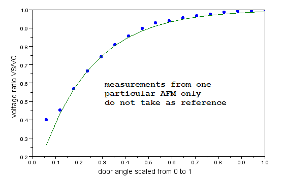
Step 4: Check resistance of VAFM per the manual, also check the resistance of Vs-E2 while moving the plate from closed to open this should be a nice smooth wave shape with no dead spots or drop outs, eg if you plot them on a graph it looks like this..
 03-04-2013, 02:25 AM
#36
Registered User
Thread Starter
Join Date: Nov 2012
Location: caroline county ,MD
Posts: 54
Likes: 0
Received 0 Likes
on
0 Posts
I don't know how to clarify that any more, you uh know how a light switch works I assume?
Off = Open circuit = Disconnected = No continuity/No connection = Power/voltage doesn't flow = The computer reads you're not idling.
On = Closed circuit = Connected = continuity = Power/Voltage flows = The computer reads you are idling.
"1 ." Is the standard DMM reading for No-connect
I feel like we've been over this before, but it might not of been you
Off = Open circuit = Disconnected = No continuity/No connection = Power/voltage doesn't flow = The computer reads you're not idling.
On = Closed circuit = Connected = continuity = Power/Voltage flows = The computer reads you are idling.
"1 ." Is the standard DMM reading for No-connect
I feel like we've been over this before, but it might not of been you 
I am trying to learn with the help of the people on this forum
And for the bottom post
 12-14-2021, 02:51 PM
#37
Registered User

Join Date: Dec 2021
Location: North County San Diego
Posts: 1
Likes: 0
Received 0 Likes
on
0 Posts
22RE bogs down under load
Does anybody know why when I touch the negative to ground on my truck with a multimeter getting power and also everytime I gas it it bogs sounds like the flapper inside my AFM but if I easily guess it sounds good sometimes sputters or makes a popping sound out of the back end and my brake light is always on does that have anything to do with it I've changed out distributor distributor cap rotor wires plugs fuel filter AFM TPS and I also clean the fuel injectors can anybody help me before I spend tons of money and also vacuum lines
12-14-2021, 06:53 PM
#38
Registered User
Forum Behavior, and How It Gets Results
Does anybody know why when I touch the negative to ground on my truck with a multimeter getting power and also everytime I gas it it bogs sounds like the flapper inside my AFM but if I easily guess it sounds good sometimes sputters or makes a popping sound out of the back end and my brake light is always on does that have anything to do with it I've changed out distributor distributor cap rotor wires plugs fuel filter AFM TPS and I also clean the fuel injectors can anybody help me before I spend tons of money and also vacuum lines
Do not take offence at what I am about to say, it is not meant to scold you.
What you have done by posting in this place is called "hi-jacking a thread"
The original poster in this thread is a non technical person trying to fix his truck.
There have been responses by some pretty savvy guys here, trying to educate him on the use of test equipment, and what the results of his measurements mean.
Now you interrupt the train of the thread, with a request to direct thought to your problem.
The guys responding to the original poster at the top of this thread probably won't redirect their attention to you, so your request will go unanswered.
Your best bet to get some help, and answers, is to start your own thread, with its own title banner.
This will ensure that your problem is the main topic of discussion in the conversations that will follow.
Please take this advice as a friendly reminder of posting etiquette, and not a angry flame.
I just wanted to see you get the help and answers to your questions that you are seeking..
Good Luck
Art.
P.S. If it were me, I would choose a forum name that didn't contain my e-mail address.
You leave yourself open to everyone with anything to sell, aluminum siding, erectile disfunction, used cars, dance lessons. and god knows what else.
Last edited by ZARTT; 12-14-2021 at 07:04 PM. Reason: More advice

Thread
Thread Starter
Forum
Replies
Last Post
89whitetoyota
86-95 Trucks & 4Runners
5
02-15-2013 05:34 PM


